01/19/2019
Prof. William Messner, Kentaro Barhydt and I decided to use hoverboard wheels as the motors to drive the cart. We also anticipated the need for some sort of encoders to be attached to the motors to determine the distance covered and speed of the motors. We know that the hoverboard motors come along with hall-effect sensors. I would like to figure out how to use these hall-effect sensors to serve as encoders in the motors.
Hall effect sensors are used in BLDC motors as a feedback mechanism to measure the speed and position of the motor rotors. The hall effect sensors, in the simplest sense, detect whenever there’s a change in magnetic flux in the rotor of the motor. A common use case is determining the RPM speed of the BLDC motor. Upon further reading and youtube video perusing, I decided to measure the RPM of the motor and then convert this into the desired distance measurement output.
Luckily the BLDC motor controller we plan to use, the ODrive V3.5, has pinouts for 3-phase hall-effect sensors for motor feedback. Hence, all we’d really do is to connect the 5 hall-effect sensor leads from the hoverboard wheels into the appropriate slots in the ODrive. According to the ODrive documentation however, the ODrive has no capacitive filtering and as a result, the hall-effect sensors are susceptible to noise. So to get consistent and clean readings from the sensors, 22nf Capacitors should be connected across each of the phase pinouts of the hall-effect sensors and ground as shown in this forum.
The ODrive has a Python interface for configuring the motors and commanding the motors to move at a specific RPM or to move for a specific number of rotations. This makes everything easier. All it needs is the right initial configuration and calibration.
03/15/2019
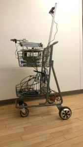
Kentaro mounted both Hoverboard wheels at the rear end of the cart. He did this by taking off the original cart wheels, increasing the diameter of the mounting hole of the right rear wheel,inserting the shaft of the hoverboard wheel through the enlarged hole and holding it in place with angle brackets. This ensured that the shaft of the hoverboard wheel was tightly attached to the shopping cart. He then did same for the left rear wheel.
05/02/2019
We have built and demo-ed Cartbot and tele-operated it to perform a variety of household tasks in our lab kitchen. A video of some of the tasks would be linked below. The remaining paragraphs below describe in detail how I designed the Cartbot control architecture.
Control System Architecture
The entire system is split into 7 subsystems; each of which is powered by one single-board computer (cite raspberry pi).The subsystems are the Motor control system, the Sensor-suite system, the Vision system, the Robot arm system, the Joystick system, the Wireless Local Area Network system and the User Interface. The user interface is the only system that runs on a standard laptop. A major value in distributing the computational duties across multiple single-board computers is that, we are able to run and fully test individual subsystems independently. Also, it removes the single point of failure in our system and establishes levels of redundancy.If one or more subsystems fail, the other subsystems that are not directly receiving messages from the failed subsystem(s) can continue to function at optimum performance. It also reduces the cost of reproducing the system on scale. The cost of having 6 single-board computers run the system is five times less than the cost of having one regular computer run the system for the same compute performance.
- The motor control system:
- The motor control system regulates all of the compute required to drive the wheels of Cartbot. It receives velocity commands from the joystick in the form of ROS Twist messages, interprets these messages and sends the corresponding motor commands to the Odrive brushless motor controller. The wheels move at a constant default velocity of 0.34m/s which can be easily adjusted bythe user. The single-board computer for this subsystem also serves as the ROS Master for the entire Cartbot. As such, it is the central point for the communication of all the other subsystems.
- The sensor-suite system:
- This system coordinates, processes and publishes the data collected by the 2D lidar and the IMU sensors. Through the data acquired from the 2Dlidar, this system detects obstacles in its vicinity and sends a message to the motor control system to halt the motors when the Cartbot is 15cm away from colliding with an obstacle.
- The vision system:
- This system processes the 3D image data from a 3D camera. It performs depth-registration on the data and generates 3Ddepth-registered color images that are then published to the appropriate topics on the ROS network.
- The robot arm system:
- This system is responsible for the arm motions of Cartbot. It receives arm velocity commands from the joystick, interprets them and sends the corresponding signals to the various controllers of the arms joints to get the arm to move in the corresponding manner. The arm ends in a pair of parallel grippers which are controlled through voice-commands using the interface.
- The joystick system:
-
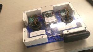
Wireless joystick control box - This system forms part of the interface through which a user interacts with Cartboat. The system is made up of two joysticks which share one single-board computer. The first joystick is for sending the mobile base velocity commands to the motor control system to move the Cartbot around. It is an 8-axis joystick which supports 8-axis directional control of the Cartbot. The second joystick is a 4-axis joystick which is used to control the arm of Cartbot. By default, the x-axis of the joystick controls the rotation of the arm about the z-axis whilst the y-axis of the joystick controls the extension of the arm outwards. To switch to controlling the elevation of the arm, the voice command elevate is said through the microphone of the User-Interface system. This sends a signal to the robot arm system to switch the y-axis control from elongation of the arm to elevation of the entire arm. To reverse this, the voice command extend is given through the microphone of the User-Interface system. The mechanical design of the joystick box [Fig. 2] was largely based around suggestions given by previous lab session participants.
-
- The Wireless Local Area Network system:
- This system provides the wireless network that connects all the subsystems of Cartbot. It is mounted onto Cartbot alongside all the other subsystems. Each subsystem is manually assigned static IP address on this network. As such, a subsystem is able to coordinate with another specific subsystem through this IP address. The Wireless Local Area Network is provided by a router (cite Net gear router)
- The User Interface:
- The User Interface enables the user to visually interact with Cartbot. It comprises of a number of features, viz;
- A command block for displaying how the robot interprets the users voice command
- A list of viable voice commands the user can give to the robot
- Live camera-feed from the robots 3D camera to display the world in the robots point of view This feature enables the user to visualize the world just as the robot sees it. It gives the user a better understanding of the robots environment and generally enables the user to better control the robot It also enables tele-operation of the robot. Since the entire system is WiFi-based,the user can control the robot from any location in the home, or even outside the home, provided the joystick computer and the User-Interface computer remain connected to the robots network.
- The User Interface enables the user to visually interact with Cartbot. It comprises of a number of features, viz;
[TO BE CONTINUED]